AutoServe
Demo
Overview
An autonomous indoor delivery robot designed to carry small payloads between locations in a multi-floor building such as a hotel. Staff load items at a base station and specify a destination; the robot navigates hallways along an A*-computed path, avoids obstacles in real time, and handles elevator floor transitions using barometric pressure detection.
A companion Python GUI on the host PC handles path planning and live mission monitoring over a WiFi telnet connection, offloading computation from the embedded microcontroller.
Hardware
The platform is a two-deck rear-drive robot built with the ECE Machine Shop. An ESP32-S3-WROOM-1-N16 handles all onboard sensing, motor control, and WiFi. Two 12V hall-encoder DC motors are driven by LMD18245 H-bridges, with a servo-mounted VL53L3CXV0DH/1 ToF sensor for obstacle scanning and a BMP585 barometer for floor-level detection.

Final robot build
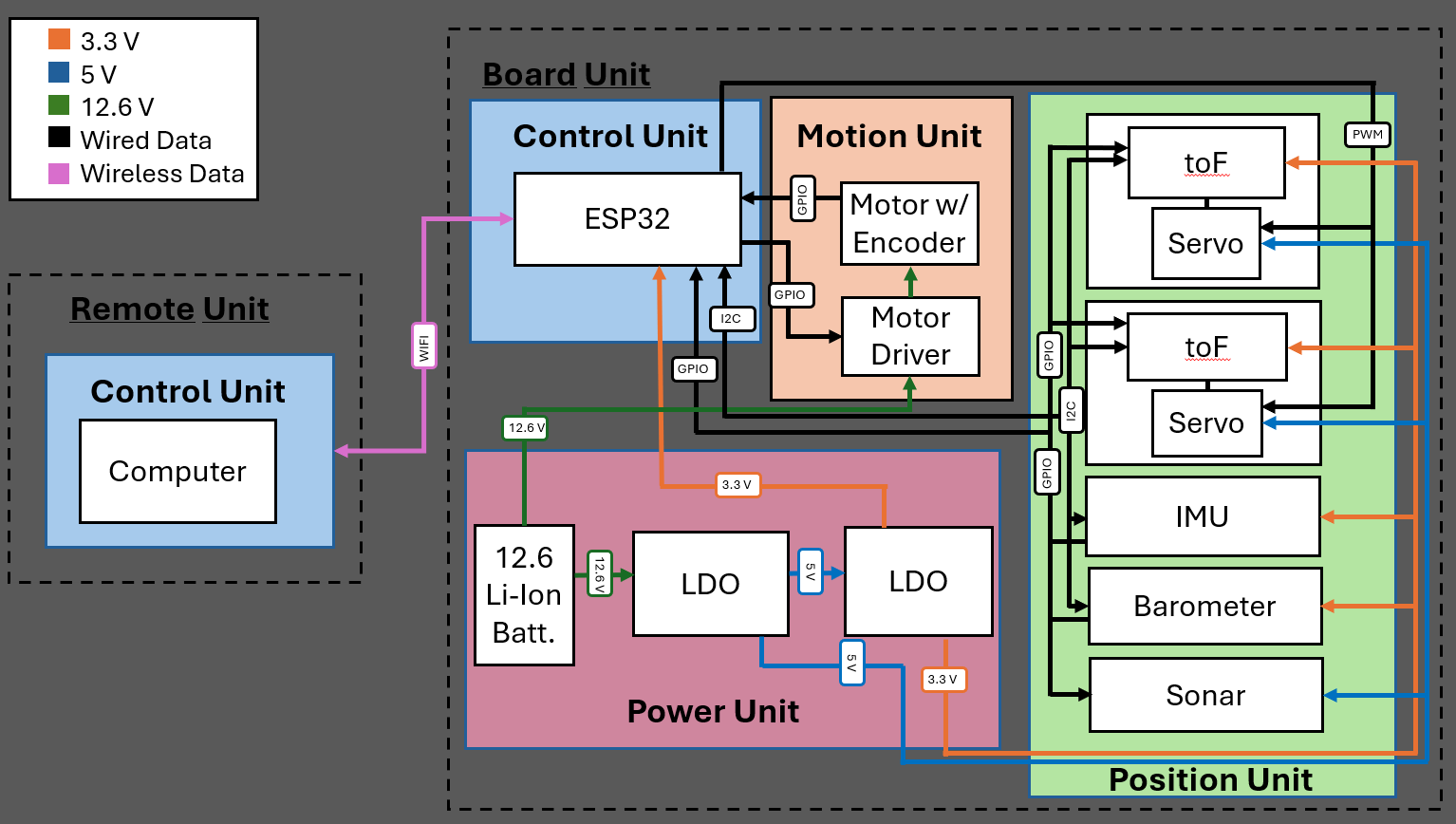
Electrical block diagram
PCB Design
The main controller PCB integrates the ESP32, dual motor drivers, power regulation, and all sensor interfaces into a single board designed in KiCad.
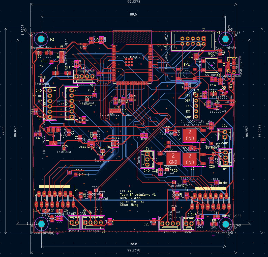
Main Controller PCB Layout
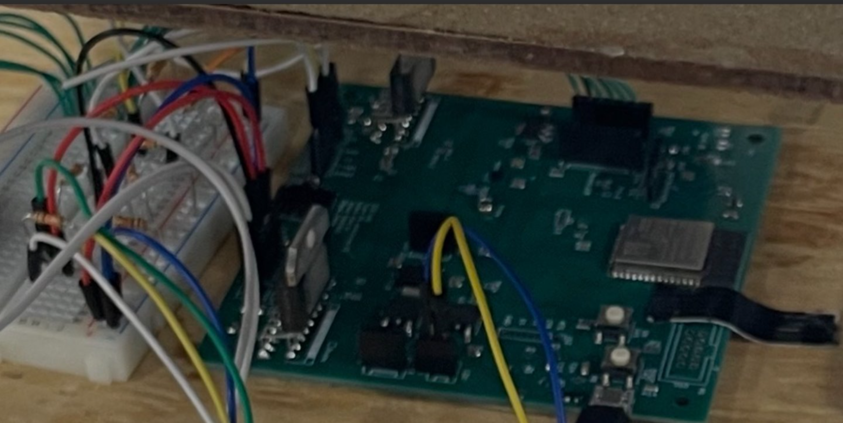
Assembled PCB mounted on the robot platform
Future Work
- Redesign chassis and wheel system to eliminate straight-line drift from caster height imbalance.
- Implement corrective motion algorithm using encoder feedback for accumulated position error.
- Autonomous map building to replace pre-loaded static floor plans.
- Extended battery life and increased payload capacity for real deployment scenarios.